February 19 2025
RF Capture #2
Stage 3 Area 1
We're given an RF capture along with the hint:
"Reverse using GNURADIO."
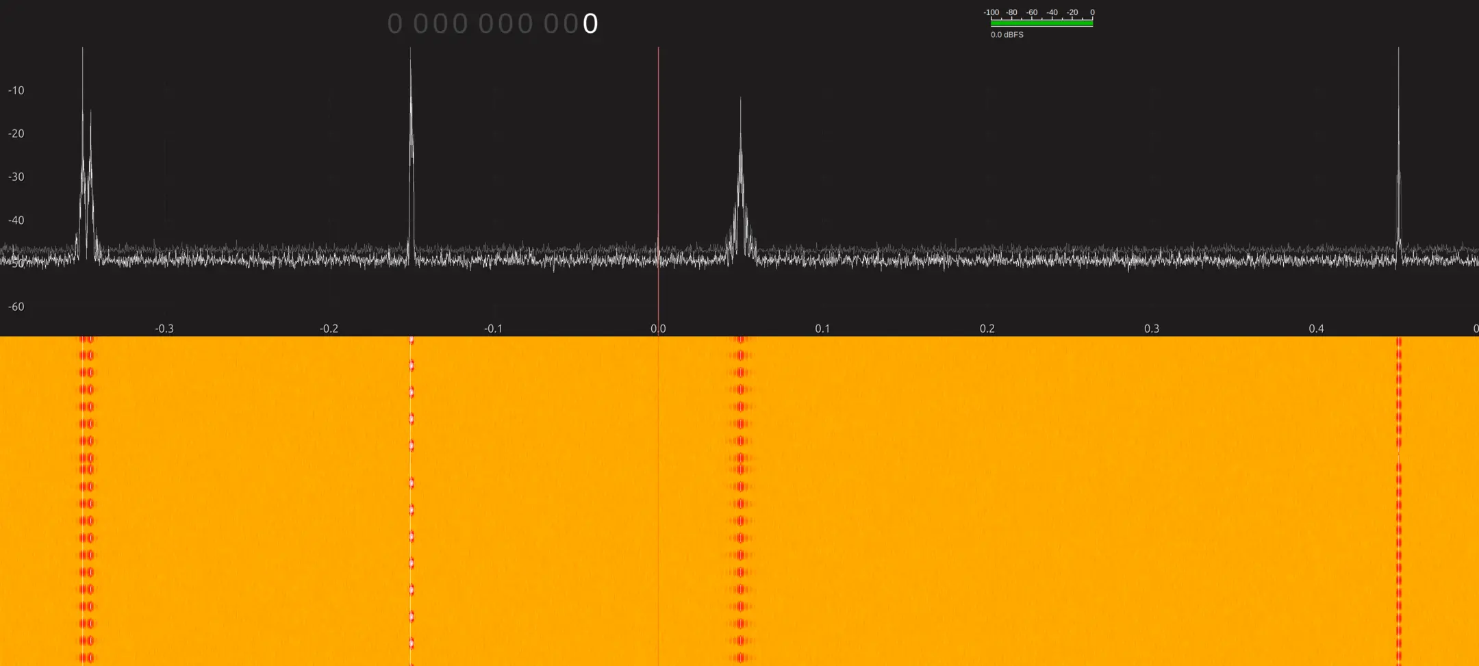
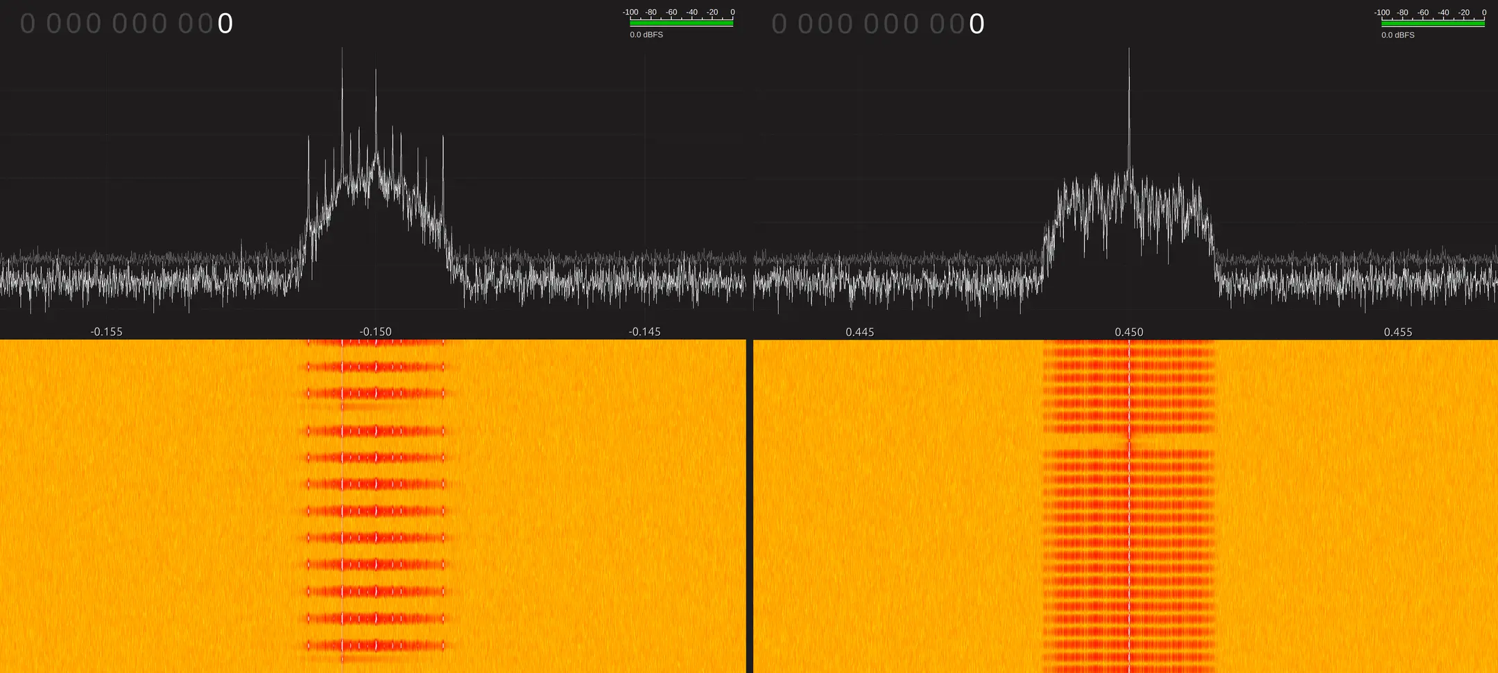
Before learning to use GNU Radio, I started with my typical workflow. Opening the capture in Inspectrum showed four distinct signals:
- -347.5 kHz - 2-FSK
- -150 kHz - GMSK-like, Manchester encoded
- +50 kHz - ASK/OOK
- +450 kHz - GMSK-like (contains the key)
At this point, the 2-FSK and ASK signals were textbook examples of their modulation, but the other two were much harder to identify. I started by demodulating the signals I could identify before tackling the ambiguous ones.
Demodulating the first two signals
-347.5 kHz (2-FSK)
This signal was textbook 2-FSK (frequency shift keying), two distinct frequencies with clear separation and very little energy in between. Inspectrum's frequency plot showed sharp, digital-like transitions between two levels, making it easy to measure the symbol rate (2.5 kBd) and export the bitstream. Decoding it produced:
UUThis is not the signal you were looking for!!!!\n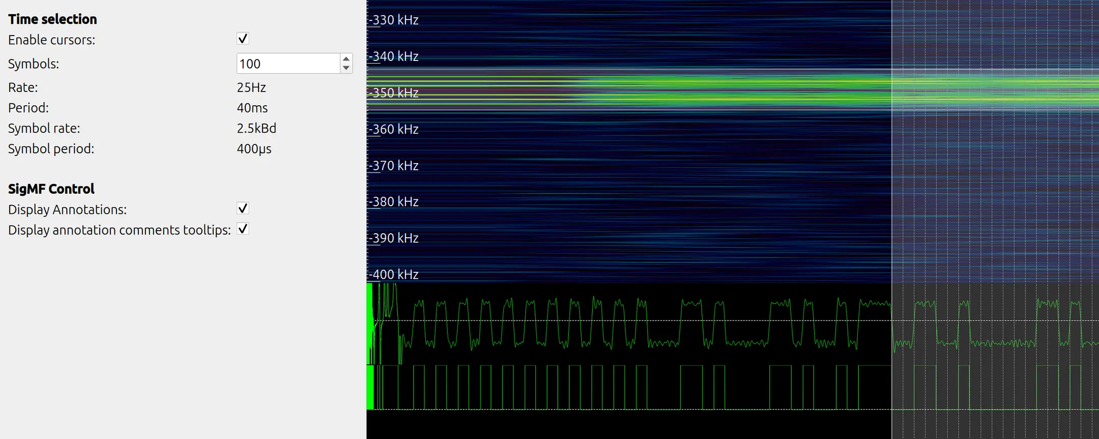
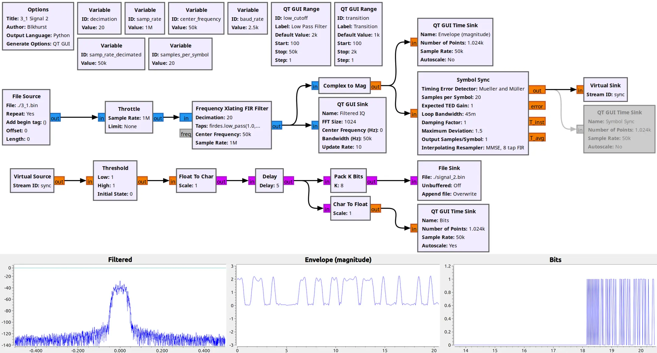
+50 kHz (ASK)
This signal was ASK/OOK (amplitude shift keying), a single carrier turning on and off in clear bursts. In Inspectrum, the amplitude plot switched between two levels, and I measured the symbol rate at 2.5 kBd, although it was too noisy to reliably threshold.
I later revisited this signal after learning the basics of GNU Radio, where I was able to easily filter and demodulate. Decoding resulted in the same UUThis is not the signal message.
Understanding GNU Radio
Up to this point I'd been relying on Inspectrum, this is when I decided GNU Radio would be required to solve the remaining signals.
To learn, I went back to the previous RF challenge (Stage 2 Area 3) to re-create Inspectrum's signal processing pipeline.
Below is an overview of the core signal-processing stages:
-
Mix to baseband (0 Hz)
Shift the signal of interest to the center, typically using an Xlating FIR Filter. -
Filtering and decimation
Once the signal is centered, apply a low-pass filter to isolate it from neighbouring signals. This stage is for signal isolation, not smoothing. A band-pass filter can be useful if not centered at 0 Hz. -
Demodulation
Convert the isolated RF signal into a waveform that better represents the symbol states.- ASK/OOK - For amplitude-keyed signals, taking the magnitude (
Complex to Mag) reveals the envelope. - FSK - For frequency-keyed signals,
Quadrature Demodconverts frequency changes into amplitude changes. - PSK - For phase-based signals, carrier recovery with a
Costas Loopcan stabilise the constellation into distinct symbol points.
- ASK/OOK - For amplitude-keyed signals, taking the magnitude (
-
Post-demodulation filtering
After demodulation, a second (matched) filter is often used to clean up and smooth the waveform. -
Symbol timing recovery
Determine the correct sampling point within each symbol period, typically using Symbol Sync. -
Thresholding / slicing
Convert the recovered waveform into binary values using blocks such as Binary Slicer or Threshold.
Identifying the remaining signals
The remaining -150 kHz and +450 kHz signals didn't look like textbook examples of anything I'd seen before. Rather than guessing, I built a small GNU Radio identification flowgraph to rule out modulations.
For each signal, I exposed sliders for frequency, filters, deviation/gain, then compared:
- Complex to Mag - amplitude/envelope view (ASK detection)
- Quadrature Demod - frequency view (FSK-family detection)
- Costas Loop + Constellation / Complex to Arg - carrier recovery/phase behaviour (PSK detection)
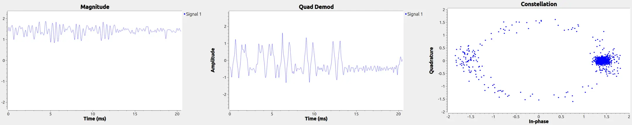
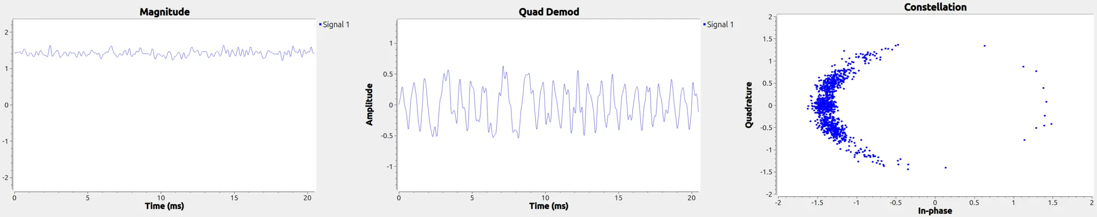
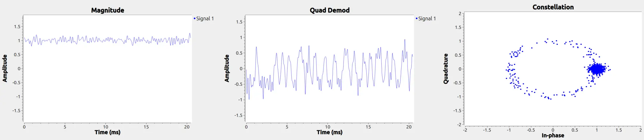
We can rule out ASK since both signals maintain a relatively constant magnitude, showing no indication of two-level switching.
We can rule out PSK because even with carrier recovery, the constellation never collapses into stable clusters (two for BPSK, four for QPSK). To confirm this wasn't a configuration issue, I generated my own PSK signal, both standard and RRC-shaped, and merged it into the capture; those produced the expected clusters, while these signals did not.
That left frequency-based modulation.
Continuous-phase / pulse-shaped FSK
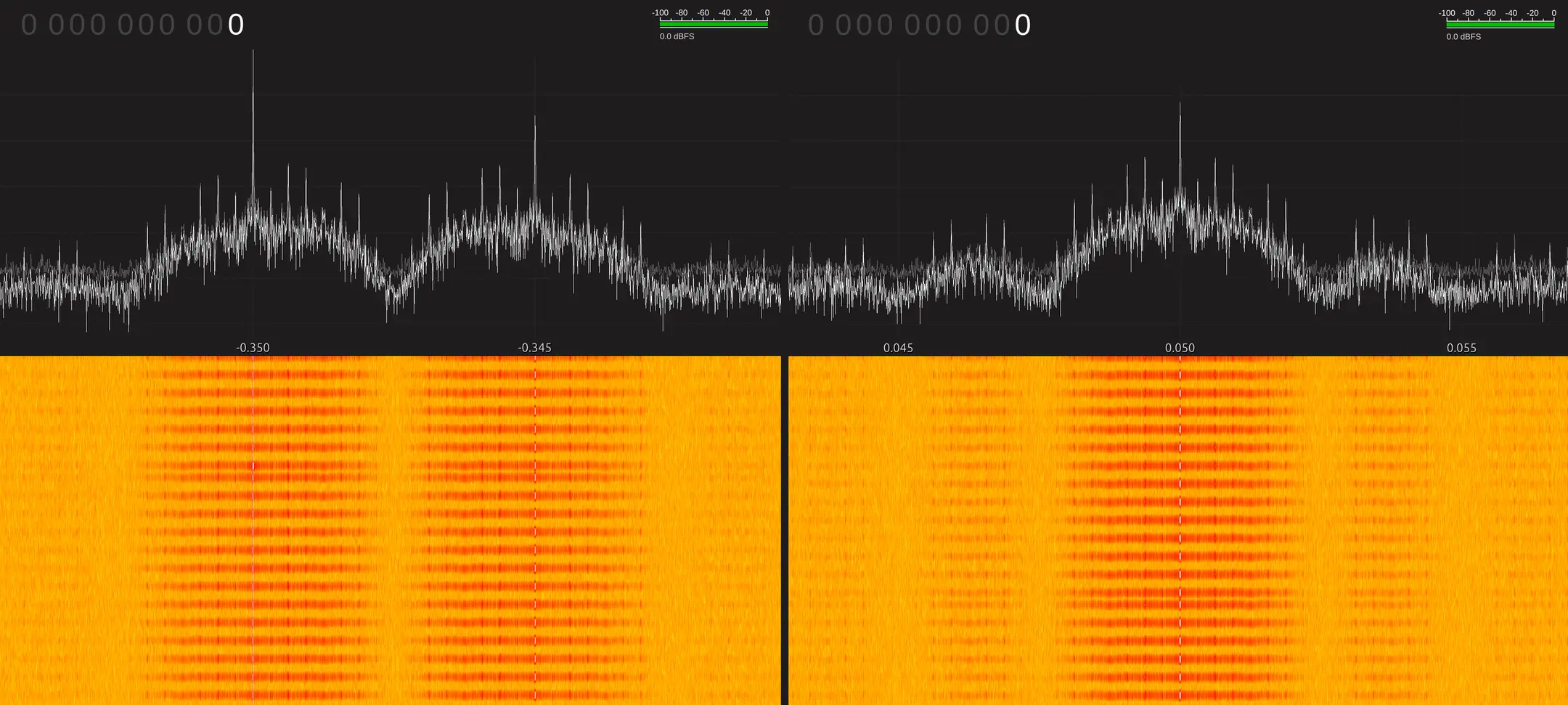
The quadrature demod output clearly contained structure, but it wasn't the clean square-like waveform of the previous BFSK signal. Instead, transitions were rounded, and the spectrum appeared as a blurred mound rather than two cleanly separated tones.
I learned these characteristics are typical of continuous-phase and/or pulse-shaped FSK variants such as Gaussian-shaped FSK (GFSK), especially when combined with the fact these signals occupy a much narrower bandwidth.
I decided to generate my own GFSK signal to compare, and the result looked almost identical. I was confident both signals belonged to the CPFSK / GFSK family. The next step was to tune the frequency deviation, before attempting demodulation.
Tuning deviation via discriminator normalisation
GNU Radio's Quadrature Demod has a gain term that depends on the expected frequency deviation, where is the (decimated) sample rate and is the frequency deviation.
Since there were no clearly separated mark/space tones, I could not reliably measure the deviation using the FFT. That's when I discovered a workflow to estimate frequency deviation by normalising the discriminator output:
- Mix to baseband and isolate the signal (Xlating FIR)
- Apply
Quadrature Demod - Add a light smoothing low-pass filter to identify plateaus.
- Sweep until the smoothed discriminator output sits consistently around .
Using this method, both signals landed at roughly . With baud, we can compute the CPFSK modulation index:
This value is significant. MSK (minimum shift keying) is the special CPFSK case where the modulation index , and GMSK is MSK with Gaussian pulse shaping. Combined with:
- it is frequency modulated
- it is constant-envelope
- it behaves like continuous-phase FSK
- it has a spectrally efficient, narrow bandwidth
- it has a modulation index of 0.5
- Gaussian filtering matches the generated reference closely
then GMSK is a very plausible fit.
Demodulating the remaining signals
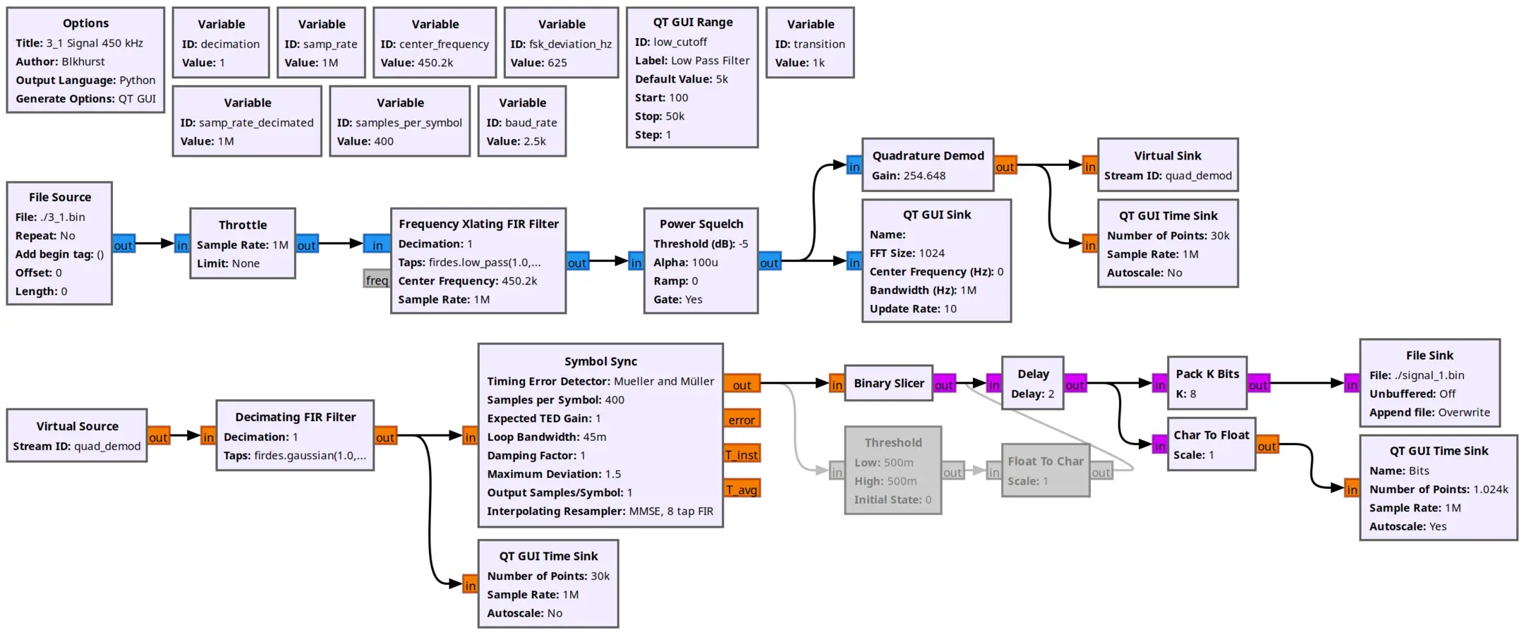
With the modulation understood, both remaining signals can be solved with the same demodulation chain:
- Xlating FIR (Mix to baseband & filter)
- Power Squelch (gate the stream when the carrier isn't present)
- Quadrature Demod (frequency discriminator)
- Gaussian matched filter (smooth / recover symbol shape,
bt=0.5, taps=4*sps) - Symbol Sync
- Binary Slicer (0/1 decisions)
Note: GNU Radio's
GMSK Demodblock with a gain of 0.1 and a leading low-pass with a cutoff of 2 kHz also demodulates both signals perfectly.
-150 kHz (GMSK-like, Manchester encoded)
This signal was Manchester encoded. I wrote a small python script that split each transmission and decoded it, resulting in the same decoy message: UUThis is not the signal you were looking for!!!!\n
+450 kHz (GMSK-like)
Unlike the -150 kHz signal, this one was not Manchester encoded, but it was slightly more challenging since the discriminator output idled centrally, causing noise for the binary slicer. A small frequency shift (200 Hz) was enough to stabilise it and make the slicer reliable.
With that adjustment, the transmission decoded cleanly and finally revealed the real key, challenge complete.
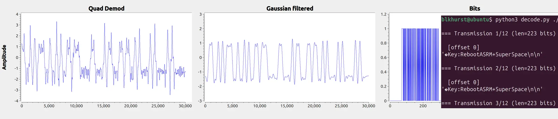
Key:RebootASRM+SuperSpace\n\n